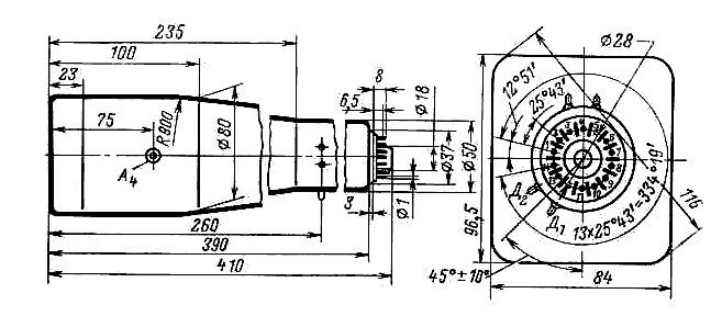
Fig
1: Physical Layout - Note deflection pins D1 - D4 260 mm from tube
face
<
11LO1I,11LO2I - 11ЛО1И, 11ЛО2И Cathode Ray Tubes
The 11LO1I and 11LO2I CRT's are single beam electrostatic deflection cathode ray tubes of Soviet manufacture. They are still available from E-Bay sellers.
Intended for use in oscilloscopes and measuring equipment, these have a a flat screen and inbuilt graticule grid lines. The 11LO1I ,11LO2I differ only in the scale of the graticule grid; both have a green phosphor. They have post deflection acceleration, which gives them high sensitivity , and makes them useful for a simple high bandwidth X-Y display. The screen size is 80 * 64 mm and the spot size is < 0.5mm square.
I have taken the data from the label supplied with the tube as well as looking round on Russian information for these, but provide no guarantee whatsoever for accuracy! The values vary between different sources; my values sit in the middle of the published values. Soviet equipment, eg. The S1-65 (Осциллограф С1-65 , schematic pdf) oscilloscope uses a cathode voltage of -2 kV, and an anode 4 voltage of 8 kV .
Electrode terminations: 1, 14 - heater, 2 - cathode, 3 – modulator grid, 4 - first anode (focusing), 5 - the third anode 7 - second anode, 9 - Screen, 10 - mesh; X1, X2 - x-deflectors; Y1, Y2 - signal deflection plates, and A - the fourth anode, 6, 8, 11, 12, 13 - not connected.
Typical Voltages (As used in the S1-65 CRO):
Uh= 6,3 V; Ua1 = 250 ... 450V; Ua2 = ± 50V; U a3 = ± 50V; Ua4 = + 8kV; Ugrid = - 30 ... -75 ; Udeflectors = ± 50V;, Ucathode = -2kV
Voltages Ux measured relative to the average value of the deflection plate potentials (normally this is ground voltage) unless stated.
It is possible to connect to all the pins with sleeved DuPont/Berg style PV cable receptacles if you don't have sockets. The HV connection for A4 is a TV style EHT “Ω” connector with a rubber boot. Both the A4 and cathode voltages are dangerous. Low current , low capacitance supplies are safest. The tube may have an internal discharge resistor (spiral) , but it would be very wise to check the power supplies and the tube are completely discharged before connecting or disconnecting any wiring to the tube.

Fig
1: Physical Layout - Note deflection pins D1 - D4 260 mm from tube
face

Fig
2: Schematic
Operating Conditions:
|
Parameter |
Min |
Max |
|---|---|---|
|
Heater Voltage - Uh |
5.7 V |
6.9 V |
|
Cathode to heater voltage |
-30 |
30 |
|
Heater Warmup Time |
- |
2 Minutes |
|
Modulator Grid M to Cathode Voltage -Um-c |
0 (-25V normal) |
-100 V |
|
A1 to Cathode Voltage - Ua1-c |
250 V |
450 V |
|
A2 Voltage - Ua2 |
-50 V |
+50 V |
|
A3 Voltage - Ua3 |
-100 V |
+100 V |
|
A4 Voltage (spiral accelerator?) - Ua4 |
+5 kV |
+9kV |
|
Screen Voltage |
-50 V |
+50 V |
|
Mesh voltage |
0 |
0 |
|
Operating Temperature |
-60 C |
+85C |
Device Characteristics:
|
Parameter |
Min |
Max |
|---|---|---|
|
Heater Current @ Uh=6.3 Volt -Ih |
0.27 Amp |
0.33Amp |
|
Modulator Grid Current - Im |
0 |
10 ľA |
|
Ia1 |
0 |
10 ľA |
|
Ia2 |
0 |
300 ľA |
|
Ia3 |
0 |
50 ľA |
|
Ia4 |
0 |
64 ľA |
|
Screen current |
0 |
5ľA |
|
Mesh current |
0 |
10ľA |
|
Current into any deflector plate Idefl |
0 |
5ľA |
|
Deflection non-linearity Y |
0 |
1.50% |
|
Deflection non-linearity X |
0 |
2.50% |
|
Deflection sensitivity Y |
2.2mm/V |
- |
|
Deflection sensitivity X |
0.7mm/V |
- |
|
Capacitance from any deflection plate to all other elements |
- |
3 pF |
|
Capacitance from modulation grid to all other elements |
- |
11 pF |
|
Brightness |
55 kLambert/M2 |
|
|
Continuous operating time |
1000 hours |
- |
Notes:
1: I have not calculated the bandwidth of the tube. The internal geometry of the tube is clearly visible, so it should be possible to estimate this. If anyone has the time and can be bothered, please let me know. The intrinsic bandwidth would be at least some hundreds of mHz , but the somewhat thin and curly wires to deflection plates would probably be more limiting.
2: The deflection current Idefl would normally be very low , but might increase suddenly if the beam is overdeflected onto the plates.
If you find errors , or have further useful data, please let me know.
![]()