A Few
Notes on the STM32F103 Series
STMF103RBT6
Brief Introduction Using Open Source Tools with
Thumb2
Tools used: gcc openocd
OS :
Linux
Getting Started
I
have used smaller single chip microcontrollers (PIC16/18 series) very
successfully, and would not suggest that the ARM processors replace
them where PICS can do the job and are the best choice.
Needing something which has 32 bit arithmetic, a larger
address space and more suited to multi-tasking, the ARM series seemed
a good choice, since it is very widely used and alternatives such as
DSP's are poorly supported by open source tools, and don't stay on
the market for long in the same form. If more processing crunch is
need there are much faster and more extendable ARM processors
available, which will run compatible source code.
The ARM/thumb2 variants are very cost effective, and made by a
number of manufacturers. I chose the STM32F103 series because it is
tolerant of a wide supply voltage range, fits well into a jtag
environment, and is easily available. The thumb2/Cortex processors
support all 32 bit functions except hardware floating point.
The ARM processors are significantly more complex than simpler
microcontrollers, but there are many more tools available, and they
offer full source software compatibility with PC's.
The datasheet for this device family can be found as CD00161566.pdf.
The big difficulty was making a start with so much information
available (and some not so readily available!). The net proved the
way to tie things together. Noted here is what worked for me (and
what did not!) . Some things took a while to figure out, such as the
unexpected incompatibility between DMA and the I2S port.
The
first approach with a simpler microcontroller such as a PIC or DSP is
to study the small but quite adequate instruction set, and the
peripherals, and then test a few small programs. All this needs only
a few quiet hours.
This is a hopeless approach with the ARM
processors. The instruction sets are as complex as the Intel Ix86 .
This means that setting up a tool chain including an appropriate "C"
compiler and debugging tools is the easiest starting point.
Being
familiar and satisfied with gcc on intel ix86, this seemed a good
choice. Unfortunately not all recent gcc versions support ARM cross
compilation correctly.
I am currently using gcc-arm-none-eabi
version 5.4.1 from Debian .
It , and the associated linker mostly run correctly. One problem which
does not seem to have an obvious solution, is that some constants are placed
in the ram section ".data' rather than the rom section ".rodata".
Strings and numeric constants are handled correctly (in .rodata section) , but constant arrays
are placed in .data (RAM), which is inconvenient both at programming and
run time.
>
The software for the target controller is
straightforward, and identical in syntax to "C" running on
the PC. Newlib provides library routines for the “C”
compiler, but it is also possible to include those available from ST
or elsewhere. GCC includes some extra object files of its own. These
are crti.o , crtbegin.o and crtend.o . Crti.o is an initialisation
procedure equivalent to the ST library file startup_stm32f10x_md.c .
Using “ld” rather than “gcc” to link the
final compiled program allows eliminating the obscure C++ routines
crtbegin and crtend which are not needed for “C”. I
recommend leaving out gcc's crti.o as well and using your own copy of
“crti”or an equivalent (eg srtartup_stm32f10x_md.c from
stm ) after looking at what it does first.
If all source files (including crti.c or startup_stm32f10x_md.c or
whatever the initialiser is called) have been compiled and put in
libraries, the first code can be specified by using the -u option on
the linker invocation. Eg. Define “mpu_reset” in crt.c
and then invoke ld “ld -u mpu_reset ...”. The linker
resolves the undefined “mpu_reset” and includes crt.c.
Crt.c then calls main and all undefined symbols are resolved in
succession by including object modules from the libraries. The
locations of the program and other data spaces must be specified in a
“.ld” file.
Programming and Debugging
Three "Arm/Keil" documents are necessary to understand the processor
core and its debugging system. These are DDI0403,IHI0031 and DDI0337.
These can be found on the net, but the later versions are only available
by signing up with Arm. The older versions on the net of these documents have
errors, which wasted some of my time. Programming the on-board flash memory
is described in STM document PM0075 aka CD00283419.pdf (was PM0042). The Jtag core is supported by "openocd" -
again you should have the right version of openocd, since versions
are all a bit different, and not all interface gadgets are supported.
I am using version "Open On-Chip Debugger 0.3.1
(2009-11-25-12:22)". Cheap "no-brand" usb/jtag
interfaces work fine, as do printer port connections using a
"XilLinx" style printer/jtag cable. I had less success with
a J-link module . The latter seem to have issues relating to firmware
versions and openocd. It would probably work with enough investment
of time.
I no longer use GDB after finding that a home cut
client using a python shell and "openocd in "gdb socket
mode" proved far easier to use, but GDB is a good starting
point.
The Arm Cortex cpu's offer two alternative debugging interfaces to the debug core; namely
JTAG or SWJ. The SWJ system saves a few pins , which can be a significant asset when
using smaller chips. This is clearly described in IHI0031C_debug_interface_as.pdf.
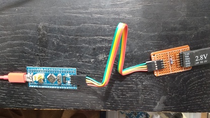
Although not strictly to spec, I have found the Xilinx style JTAG cable works nicely
with the SWJ interface with the addition of a 2.2 kilohm resistor, so long as the distance
between the 6 pin JTAG header and the cpu is not excessive. The connection is as follows:
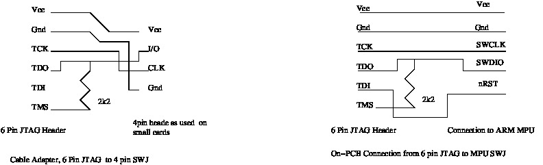
 This reconnection between the two standards may be on the cable, or on the
target board in order to make the board compatible with the 6 pin header. In the latter case
the the unused TDI pin may be used to drive nRST if desired. There is no accepted standard for
JTAG headers, and many different types are used. It worth having some adapters if commercial PCB's are used.
I have found the original 6 pin single row 2.54mm header quite satisfactory for PCB designs,
so long as some mechanical provision is made ensure correct positioning. If
right angled pin-strip is used as shown, then the connector can not be inverted.
This reconnection between the two standards may be on the cable, or on the
target board in order to make the board compatible with the 6 pin header. In the latter case
the the unused TDI pin may be used to drive nRST if desired. There is no accepted standard for
JTAG headers, and many different types are used. It worth having some adapters if commercial PCB's are used.
I have found the original 6 pin single row 2.54mm header quite satisfactory for PCB designs,
so long as some mechanical provision is made ensure correct positioning. If
right angled pin-strip is used as shown, then the connector can not be inverted.
It is useful to scan for the JTAG chain, and if it is not present then switch to the
SWJ interface automatically. The on chip interface is hierarchical, and the debugging level
of the interface is shared by JTAG and SWJ; the debug operation is identical for both
connection styles. I have used this method on both STM32F103 and STM32F4xx devices, and
found no problems. This enables the same Xilinx style 6 pin cable to connect directly
and transparently to a target system irrespective of whether SWJ or JTAG is used. If
the nRST pin is routed to the TDI pin on the cable header with SWJ , then the debugger
can override any pin mapping without needing a manual reset.
The advantages of using JTAG are its ability to connect multiple devices of various sorts
in a chain, and to be able to use boundary scan testing. Both interface styles have their
place. The STM chips show two Jtag devices in the chain, the STM part for boundary scans, and
an Arm-Cortex part for debugging. The SWJ interface does not offer boundary scanning.
The pins used for debugging can all be remapped for I/O after reset. There
are some inconsistencies in the case of the STM4xx where a JTAG pin can be remapped even though not
specifically requested. This is documented in ST errata. The way round this is to
assert the reset pin before debugging. In general, if pins are scarce, it is better to use SWJ.
The debug (SWJ or JTAG) core allows fairly complete control over the chip. It is
possible to single step programs and alter memory as desired.
Breakpoints can be set and cleared. If the debugging (-g) option is
set when compiling, then extensive debugging information (e.g. memory
locations,line numbers and structures) is included in the “.debug”
section of the assembly code. Assembly listings can be generated by
compiling the “C” code to assembly (.S) files with gcc,
and further compiling these using “as” with option
“-a=outfile.lst”. The symbol debug information in the
assembly file is cryptic, but is easily displayed in a self
explanatory useful format by typing “readelf filename.o”.
This information is described in the documentation for “Dwarf”.
Debugging a multi-tasked program with lots of swapping , and tasks
coming and going in a real time situation, is hardly helped by
breakpoints and single stepping,and the only really useful way of
tracing random occasional faults is to use a rotating/refreshed
variable storage buffer, and try to detect an incipient fault
condition and halt.
Reset Issues
There are two methods of applying a reset to a chip connected via JTAG
or SWJ, either hardware or software (AIRCR register). There are two
reset request bits, SYSRESETREQ and VECRESET. VECRESET is more likely to
work.
Unfortunately it seems possible for the chip to go deaf to any memory accesses,
making a software reset using AIRCR impossible.
I have found only two ways out of this state; one must either apply a low signal to
the nRST line, or remove power from the device. Since smaller cards do not
have provision for the reset signal, removing supply for a fraction of a second
can be the easiest way of avoiding the need for a manual reset.
I/O and Peripherals
ST provide library functions for initialising and controlling most
of the on chip peripherals. These provide a good introduction/howto ,
but are a bit cumbersome, and it is often easier to simply set the
appropriate registers.
It is essential to read the manual
to understand how the clocks are enabled for the CPU and the
peripherals. The STM examples show how this is done. Virtually all on
board peripherals (including simple ports) have clocks which
must be enabled and configured before use. If a watch crystal (32
khz) is used, then it must be a low capacitance type or operation
becomes unreliable.
STM have published libraries of
subroutines and examples for their chips, and these all work fine
with gcc, but need a bit of patching to suit the specific hardware. I
have run test programs for the USB,ADC,DMA,TIMERS,PWM,RTC , various
clock sources and UARTs , all of which worked satisfactorily and
easily, except for the following difficulties:
The USB example needs a bit of peculiar wiring to generate a
reset/disconnect (see USB
Reset Signaling , ST AN1815 ). The I2S port does not interact in
a useful way with the DMA core, which proved a nuisance when driving
an ENC28J60 ethernet chip. The ADC showed a bit more noise than I
liked. In every other respect the chip worked very well.
Interrupts
The thumb2 processor does not require specific interrupt exit
and context saving, since the cpu sets the LR register to flag
interrupt return addresses automatically, allowing a normal "C"
subroutine serves as an interrupt routine without needing special
code.
It is useful to have all interrupt vectors used by the
interrupt controller (NVIC) defined in a link script as "pragma
weak", which will be replaced automatically if an appropriately
named interrupt routine is included. It may be necessary to remove at
least one vector defined as “pragma weak” to ensure the
linker (“ld”) notices an unresolved variable and
includes the interrupt handler if this is not specifically included
in the linker script or invocation line,
Exceptions, SVC , Context
Switching and Inline Assembly Code
Inline assembly language is not needed at all for simple programs.
It is only necessary for context switching, threading, and privilege
controls.
Some commonly used sequences, such as incrementing a non-stack
pointer or variable are done badly by gcc, which loads the pointer to
the variable twice. Since thumb2 instructions need two steps to load
an address, this behavior costs 2 extra instructions for each
variable loaded or stored. For this reason an inline assembly macro
to do increment/decrement operations is a useful cycle saver.
Inline code embedded within gcc “C” code is
straightforward and it is not necessary or advisable to write
complete assembly routines. Best practice is to embed all inline
assembly within “#define” statements in a separate “.h”
file. The file I use is cdefs.h
; the included definitions were sufficient to avoid including any
in-line assembly in the body of a multitasking routine.
The thumb2 instruction set codes are helpful in debugging this
sort of code. On entry to an interrupt/exception the registers
R0,R1,R2,R3,R12,LR , then return address , then PSR with R0 lowest
are placed on the stack located by stack pointer MSP. This latter
sequence seems different to that given by STM (Doc ID 15491 –
“Cortex Programming Manual”) which shows LR highest on
the stack!
If writing an exception handler in “C”, and access to
these stacked values for context switching or an SVC code is needed,
then the handler procedure may be qualified as "bare" “
__attribute__( ( naked ) ) “ to avoid losing the position on
the stack. This attribute causes gcc avoid stacking registers, and
causes it to use register variables rather than locations on the
stack (making it execute faster!); the final “BX LR”
(return) instruction is also omitted. It is a good idea to check the “.S”
output of gcc to see what actually happens, since gcc adds
instructions automatically and not always predictably.
GCC tends to use lower numbered registers for variables and pointers.
It makes sense to use higher numbered registers for in line assembly
code in bare routines to reduce the likelihood of conflicts. The Arm Thumb2
has plenty of registers, so it is not hard to avoid conflicts, but is
essential to check.
For some incomprehensible reason the visibility of bit 2 of the
CONTROL register is masked to zero while in exception mode, making
the bit inaccessible during exception handling, so an exception
handler cannot easily determine which stack pointer an interrupted
(calling task) is using. This means that it makes sense to reserve
the MSP exclusively for exception handling or for unthreaded
programs. In the case of unthreaded programs the “ __attribute__( ( naked ) ) “
may be omitted since the PSP is not affected.
If a “bare“ exception handler needs to use a non-bare “C“ subroutine
it is necessary to save the LR register or restore it to 0xFFFFFFFD (EXCEPT_RET) and set
the frame pointer (R7).
If no data is to be passed on the stack, then R7 can be set to zero. Any parameters
passed from a bare routine are best register variables (eg. int or pointer).
Context switching can be complicated by preemptive exception entry
(“late arriving”) and to a lesser extent “tail-chaining”
causing conflicts between SVC calls (needed to change privilege etc)
and the context switch interrupt handler. This can be avoided by
setting the priority registers to prevent this, or by testing bits in
the handler status register ( SCB_SHCSR bits 7,15) and not context
switching (skipping a time slot) while an SVC is active. The former
approach uses a few less processor cycles, the latter makes task
queue handling in an SVC easier. See exception handling in Cortex
M3 Technical Reference Manual.
Be wary of placing comments in any in line assembly. Either format
of comment , C or C+ in an assembly macro line can cause weird results.
Some words of warning – if you accidentally use a non thumb2
ARM instruction the gcc assembler may accept it without error, also
if you have not properly specified thumb2, gcc may generate thumb
instructions only which may run ok, but are significantly less
efficient. If calling a normal unqualified gcc subroutine from an
exception handler qualified by “ __attribute__( ( naked ) ) “
then the LR register must be saved before calling and restored
afterwards (eg asm( "STMDB SP!, {LR}"
);sub_called();asm("LDMIA SP!, {LR}" or if, e.g. using
“#define” statements (as in cdef.h) above then
svregs();sub_called();getregs();
Option Bytes
Some functions (memory protection,booting and watchdog) of the microcontroller are defined by “Option Bytes“ (See PM0075).
To change these they must be erased first. Erasure sets read protection on, and forces a program erase before
any further change to these bytes is made.
While read protection is set almost all functions of the debug interface are disabled except for resetting the option bytes.
If an attempt is made to access a protected location then power is removed from the debug domain until a debug domain power-up and a reset are
issued.
Once the protection bytes are erased, then the value 0Xa5 must be written into
the lowest option byte. At this point the processor must be reset (from
my experience only a hardware reset is reliable) before programming the remaining bytes.
This behaviour is documented in the programming manual.
Compatibility with STM4xx series
ST have a similar processor family (ST32F4xx) with an enhanced instruction set including
floating point, as well as significantly higher clock rate and more ROM and RAM. It is fairly different
in terms of flash programing and register allocations, and far from a drop in replacement.
It is possible to use it as a compatible upgrade if the numerous differences are
taken into account. The flash programming of this series uses different bit widths for different
supply voltages, whereas programming of the STM32f1xx series is always word (16 bit) wide. The
programmer for the STMF4xx does not necessarily know the supply voltage,making the choice of
programming width problematic. I have found using 16 bit (PSIZE=1) works reliably for 3.3V > Vcc > 2.5V if you do not need the
faster time and want compatibility with the STM32F1xx series .
Much documentation is available from the ARM/Keil
site, but access to some of this requires user registration.
Other
links I've found useful (other than the easy to find Wikis etc.
on ARM,Thumb2).
Documentation
Getting
Tools; GCC,OPENOCD etc
STM32
Summary
Info
on CMSIS and Code Sourcery
Inline
Assembler CookBook : Necessary for context
switching/multitasking/SVC calls
The
thumb2 instruction codes were here If it is no longer get
DDI0403D_arm_architecture_v7m_reference_manual_errata_markup_1_0.pdf
from www.arm.com